
Introduction
When we announced our TR-8oh8 CPU upgrade, one concern we heard was:
“Will that upgrade perfectly capture the groove of the original CPU?”
In this article, we discuss where that specific groove comes from and how well we can recreate it with our TR-8oh8 CPU. We also show how we can even improve the timing.
The specific groove of a drum machine can be caused by many factors. For example, the way the sounds interact with each other, how dynamics are processed, and how precise the timing is. For our CPU, only the timing aspects are relevant, because the other factors are part of the non-CPU hardware.
Timing accuracy can be expressed as a function of jitter and latency with respect to a reference clock signal.
- Latency: the time between the clock and the actual drum trigger
- Jitter: The variation in latency
Why does the original TR-808 exhibit jitter and latency?
The original TR-808 is clocked either from its internal clock or an external DIN-sync clock. The internal clock can be assumed to be jitter-free *. An external clock could theoretically have any amount of jitter, as its quality is fully determined by the gear sending it.
A strongly jittering external clock would change the 808’s ‘groove’. This interaction is not covered in this article.
In the 808, the clock signal is sampled by the CPU, which will then generate the triggers for the drums.
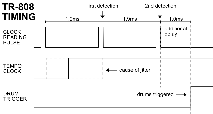
Interestingly, this sampling is not interrupt-driven, but rather the clock signal is sampled at a rate of 1.9ms. The reason for this is that reading the clock signal is time-multiplexed with reading the switches.
This design decision causes 1.9ms of jitter between a rising clock edge and the drum-trigger output.
Another interesting choice is that the TR-808 samples the clock signal twice before outputting a trigger. Presumably, this was done for debouncing purposes, but is of questionable usefulness as the clock signal already has proper edges.
An assumption is that the debouncing algorithm used for the switches was accidentally also applied to the clock reading.
In any case, this automatically adds a latency of 1.9ms.
The TR-808 exhibits an additional latency, though: There is a roughly 1ms delay between the second clock reading and the actual output of the trigger. We did not reverse engineer the original firmware, but this might be the CPU needing some time to read data from the RAM.
Jitter and Latency of the original TR-808
The resulting jitter and latency are: 2.9ms latency + 1.9ms of jitter. This is quite bad for today’s standard, but might be an explanation for the TR-808’s specific ‘groove’.
TR-8oh8 legacy clock mode
The TR-8oh8 can easily emulate this behavior: We use the same interval of 1.9ms to read the clock signal. Furthermore, we can add an appropriate delay between reading the clock and outputting the pulses. This results in the same timing as the original:
2.9ms latency + 1.9ms jitter
TR-8oh8 improved clock mode
On the other hand, we can actually do better: Read the clock signal more often. Do not wait 2 periods to process the clock signal. Do not add 1ms latency.
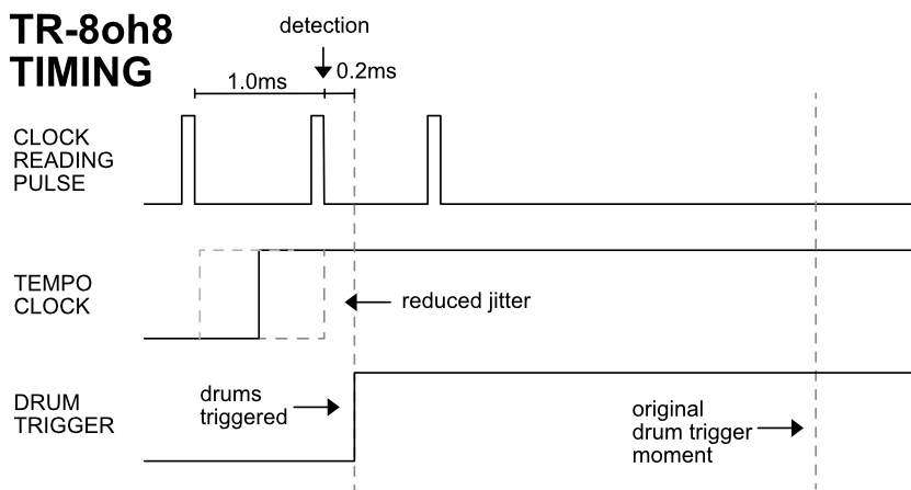
In the improved clock mode, we read the clock signal with a period of 1ms, instead of 1.9ms. This practically halves the jitter. We can not reduce the jitter further, as we are also bound by the multiplexing hardware.
We also have much faster processing, reducing the latency substantially:
Only 0.23ms latency + 1.0ms jitter.
Your choice
The improved clock mode exhibits overall better timing, but with the danger of sacrificing the ‘groove’. We therefore decided to implement both the original timing and the improved timing. You can easily switch between them in the config menu.
* Compared to the huge jitter of the TR-808, the clock’s jitter can be neglected.
Pixie CPU
We also measured the timing of the Pixie CPU used by the RE-808 project. Apparently, it uses a 1.7ms instead of 1.9ms timing period. Unlike with the original, this period can also not be adjusted by calibrating the interrupt clock.
So at least from a theoretical standpoint, the Pixie CPU does not perfectly emulate the TR-808’s ‘groove’.