TR-808 timing, groove and jitter

Introduction

When we announced our TR-8oh8 CPU upgrade, one concern we heard was:
“Will that upgrade perfectly capture the groove of the original CPU?”

In this article, we discuss where that specific groove comes from and how well we can recreate it with our TR-8oh8 CPU. We also show how we can even improve the timing.

The specific groove of a drum machine can be caused by many factors. For example, the way the sounds interact with each other, how dynamics are processed, and how precise the timing is. For our CPU, only the timing aspects are relevant, because the other factors are part of the non-CPU hardware.
Timing accuracy can be expressed as a function of jitter and latency with respect to a reference clock signal.

  • Latency: the time between the clock and the actual drum trigger
  • Jitter: The variation in latency

Why does the original TR-808 exhibit jitter and latency?

The original TR-808 is clocked either from its internal clock or an external DIN-sync clock. The internal clock can be assumed to be jitter-free *. An external clock could theoretically have any amount of jitter, as its quality is fully determined by the gear sending it.
A strongly jittering external clock would change the 808’s ‘groove’. This interaction is not covered in this article.

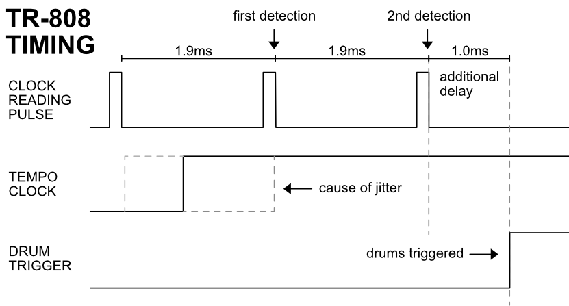
In the 808, the clock signal is sampled by the CPU, which will then generate the triggers for the drums.
Interestingly, this sampling is not interrupt-driven, but rather the clock signal is sampled at a rate of 1.9ms. The reason for this is that reading the clock signal is time-multiplexed with reading the switches.
This design decision causes 1.9ms of jitter between a rising clock edge and the drum-trigger output.

Another interesting choice is that the TR-808 samples the clock signal twice before outputting a trigger. Presumably, this was done for debouncing purposes, but is of questionable usefulness as the clock signal already has proper edges.
An assumption is that the debouncing algorithm used for the switches was accidentally also applied to the clock reading.
In any case, this automatically adds a latency of 1.9ms.

The TR-808 exhibits an additional latency, though: There is a roughly 1ms delay between the second clock reading and the actual output of the trigger. We did not reverse engineer the original firmware, but this might be the CPU needing some time to read data from the RAM.

Jitter and Latency of the original TR-808

The resulting jitter and latency are: 2.9ms latency + 1.9ms of jitter. This is quite bad for today’s standard, but might be an explanation for the TR-808’s specific ‘groove’.
TR-8oh8 legacy clock mode

The TR-8oh8 can easily emulate this behavior: We use the same interval of 1.9ms to read the clock signal. Furthermore, we can add an appropriate delay between reading the clock and outputting the pulses. This results in the same timing as the original:

2.9ms latency + 1.9ms jitter

TR-8oh8 improved clock mode

On the other hand, we can actually do better: Read the clock signal more often. Do not wait 2 periods to process the clock signal. Do not add 1ms latency.

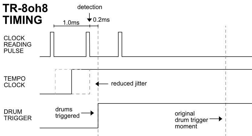
In the improved clock mode, we read the clock signal with a period of 1ms, instead of 1.9ms. This practically halves the jitter. We can not reduce the jitter further, as we are also bound by the multiplexing hardware.
We also have much faster processing, reducing the latency substantially:

Only 0.23ms latency + 1.0ms jitter.
Your choice

The improved clock mode exhibits overall better timing, but with the danger of sacrificing the ‘groove’. We therefore decided to implement both the original timing and the improved timing. You can easily switch between them in the config menu.


* Compared to the huge jitter of the TR-808, the clock’s jitter can be neglected.

Pixie CPU

We also measured the timing of the Pixie CPU used by the RE-808 project. Apparently, it uses a 1.7ms instead of 1.9ms timing period. Unlike with the original, this period can also not be adjusted by calibrating the interrupt clock.
So at least from a theoretical standpoint, the Pixie CPU does not perfectly emulate the TR-808’s ‘groove’.

Midi for Korg Lambda using OrganDonor

Overview

The Korg Delta version of OrganDonor offers the following features:

  • Fully polyphonic midi input for all 48 notes
  • Optional learn button to set midi channel.

Installation

The installation is relatively simple, but does require basic soldering skills. You will need to drill a hole for the midi socket.
Installation instructions can be found in this PDF.

User guide

Setting midi channel and keyboard offset

If the optional learn button is installed, it can be used to quickly change the midi receive channel of organDonor.

Connect midi out of a computer or keyboard to midi in of organDonor. Make sure not to send any notes.
Press the learn button and while it is pressed send a midi note on any midi channel. organDonor will set this note as the lowest note of the synthesizer and use its midi channel. These settings are saved.

Playing notes

Send midi notes on the configured midi channel (see above)
By default, this is midi channel 1.

More configuration

Alternatively you may configure a lot of parameters using our organDonor configurator.
We recommend using the Korg Lambda config file as starting point
1.) Save the file on your hard drive via right click -> save as
2.) in the configurator press “Load configuration” and select the file

CeeS software controller

CeeS Cntrl is a GUI interface to Tubbutec’s CeeS MIDI retrofit for Yamaha CS5, CS10, CS15, CS15D, CS30 and CS30L synthesizers, adding MIDI input and output as well as additional filter modulation sources.

The interface follows the CeeS MIDI controller chart and maps MIDI CC values to knobs, buttons and menus that can then be automated in a DAW. The app is resizable and the About CeeS Cntrl screen displays credits and a starter patch for easy reference. A printable version of the starter patch can be opened in your browser. Patches can be saved to the DAW host. Double-clicking a knob will reset its value to zero.

Adding MIDI to a Wersi Bass synthesizer

This guide explains how to install MIDI in a Wersi Bass Synthesizer using our OrganDonor interface.
Installation and pictures by AudioCircus . Thank you

You will need an organDonor with 3 switch boards. Each of the boards will control one octave of the synth.

The organDonor main board and switch boards can be fixed in the synth’s case as shown and need to be wired up as follows:

  • For each switch board, connect the first 12 common signals using the solder bridges on the back
  • Solder a wire to each common connection (3 wires total).
  • Connect the 12 analog switch outputs using a common ribbon cable. We can provide such a cable on request, or you can crimp your own

Next, solder the 12 wires and the 3 common wires to the back of the board as shown here:

Organ Donor will also need power.

In the organDonor configurator, you can select the MIDI notes for the switches you used. After uploading the configuration, MIDI input should work.

Adding MIDI to an Oberheim TVS (Two Voice)

Image by Alison Cassidy, CC BY-SA 4.0

Thanks to Rob Rosen of Rosensound we now have an uniMatrix install guide for the Oberheim TVS (Two Voice). This only works for the Matrix keyboard version (see install guide). For the older version, you can probably use OrganDonor instead.

The upgrade allows MIDI note input and filter cutoff control.

Download the install guide as PDF here, the config file can be downloaded here.

US tariffs, De Minimis, and shipping

From August the 29th 2025, the US will stop the De Minimis exemption on imported goods from the EU. Previously, US customers did not have to pay tariffs on goods below a total value of $800.

Beginning on August 29th, US customers will incur a 15% tariff charge.
Furthermore, for the first 6 months, orders shipped via mail (anything that is handled by USPS) will face a flat $80 import charge—no matter the value.

Shipments handled by a 3rd party, however (DHL Express, UPS, FedEx…), will be properly charged with 15%.
For this reason, we have deactivated our mail shipping methods for the US. Customers can now only select DHL Express. It’s about 39€, so still affordable.
You will be charged with 15% import duties by DHL upon import, not during checkout.

Update:
Since writing the above, German mail (Deutsche Post / DHL) and many more mail services around the world have stopped shipping goods to the US entirely. DHL express does still work, so the above is still true.

A note about the 15%: Yes, it’s not great to pay more. If it is any comfort, people in the EU have pretty much always had to pay between 15% and 25% of VAT.
So in a way, you at least still don’t have to pay more than EU customers.

MIDI for Korg PS3100

This guide shows how to install our OrganDonor upgrade into a Korg PS-3100 synthesizer. The installation is pretty easy: You will basically just need to solder one wire for each key. Currently, this manual shows how to get basic note on/off control, but might be updated with control over the filter and other parameters – this is already supported by the organDonor hardware.

Thank you very much to Ty Hodson who not only figured out how to install the kit, but also wrote a detailed instruction guide.

Download installation instruction as PDF here.

MIDI for Casio SK-1 using uniMatrix

This guide explains how to install a MIDI input in a Casio SK-1 keyboard. We use uniMatrix to interface the keyboard matrix and simulate key presses.
The default configuration plays notes from C3 (Midi note 36), but this can be changed.

It is also possible to change instruments via MIDI program change messages.
ProgCh 0: Piano
ProgCh 1: Jazz Organ
ProgCh 2: Pipe Organ
ProgCh 3: Flute
ProgCh 4: Trumpet
ProgCh 5: Synth drums
ProgCh 6: Trumpet
ProgCh 7: Brass
ProgCh 8: Sampling sound
ProgCh 9: Harmonic Sound

The following CC control is also implemented:
CC 5: Portamento ON/OFF
CC 6: Harm Synth
CC 7: Env select
CC 8: Vibrato ON/OFF

Installing uniMatrix

Use double sided tape to mount the uniMatrix board to the big IC on the SK-1 board. Then, solder the wires to the points shown in the picture below. The numbers are the uniMatrix I/O numbers. Do not rely on the wire colors in the picture, these might be different in your version of uniMatrix.
Solder the two power wires Vin and GND to the points shown.

Overview

Solder points for uniMatrix I/Os

Solder points for uniMatrix power

Finally, drill a hole in the back using the drilling stencil provided in the kit, mount the MIDI socket using the two M3 bolts and plug it into the MIDI in connector of uniMatrix.

Using the uniMatrix configurator, load the configuration for SK-1 (right click, save-as) and send it to uniMatrix.

Congratulations, you can now play your MT-90 via MIDI !

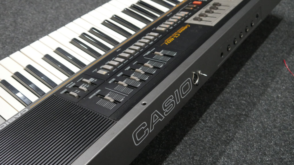
MIDI for Casio CT-410V (MT-400V)

This guide explains how to install a MIDI input in a Casio CT-410V keyboard. It will probably also hold true for the very similar MT-400V.
We use uniMatrix to interface the keyboard matrix and simulate key presses.
It is also possible to sync the rhythms to the MIDI clock and to start/stop via MIDI.

With the current config file, you can play all notes and start/stop via CC 67. Though this can easily be changed with the configurator, for example to achieve start/stop via a special note.

Installing uniMatrix

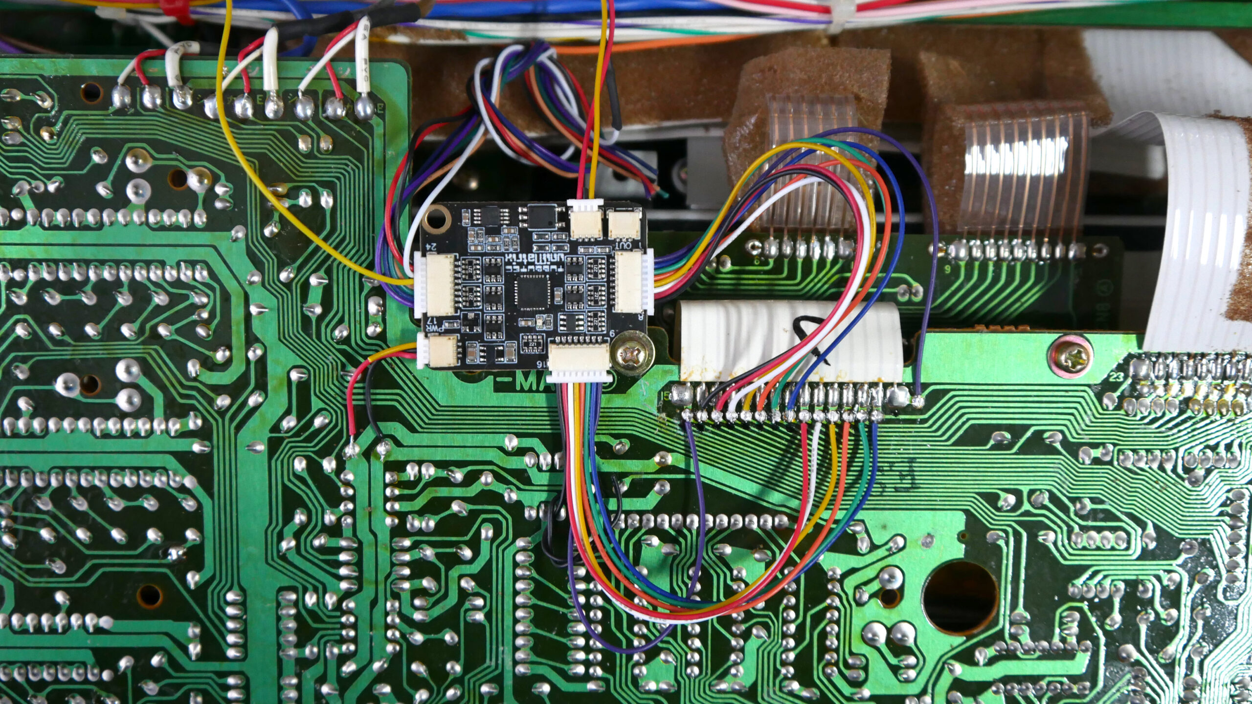
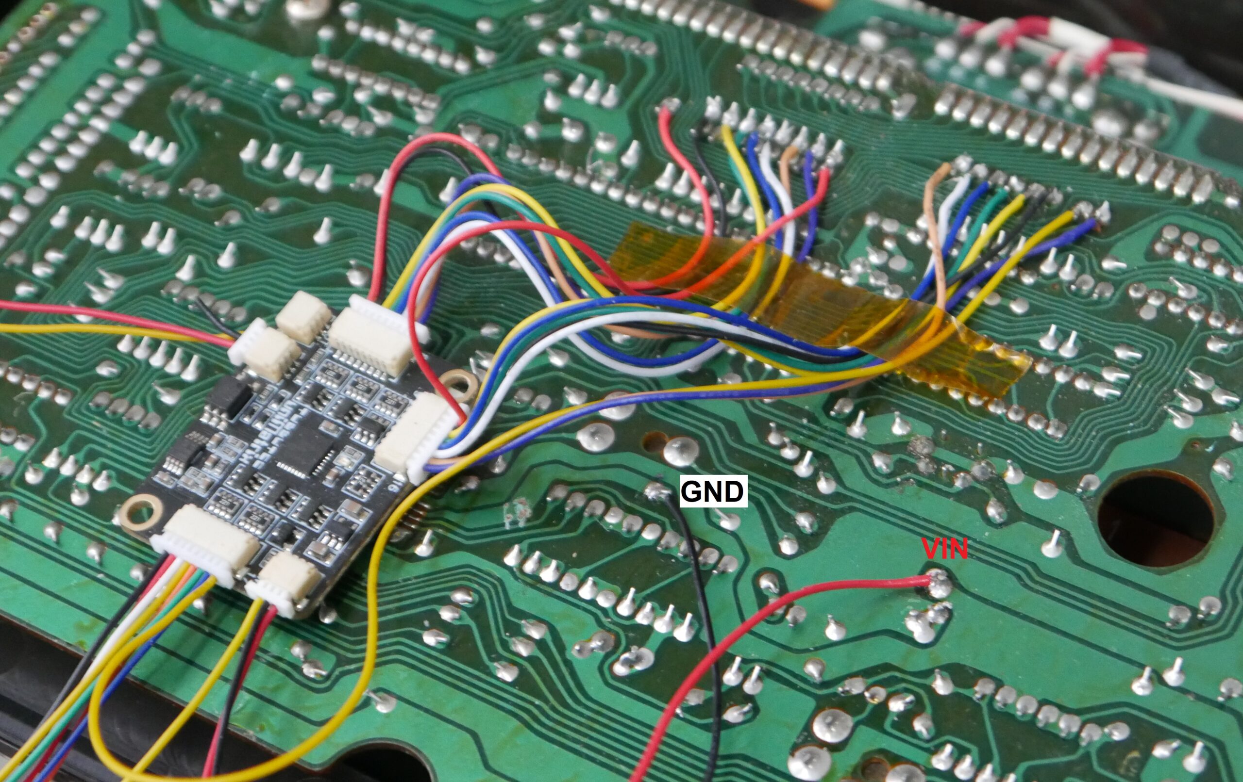
After opening the keyboard by removing the screws on the bottom, the uniMatrix board can be conveniently mounted with the existing screw as shown in the picture below. The red and black power wires on the left are soldered as shown (please ignore the yellow wire).
Next, solder uniMatrix IO1-15 to the points shown below. (click on the picture for a larger version)

The colors of the wires might be differernt for you. Please refer to the pin numbers instead. The pin numbers are printed on the uniMatrix circuit board (1 … 8, 9 .. 16, 17 … 24 ). The corresponding pin locations are marked with numbers in the image above.

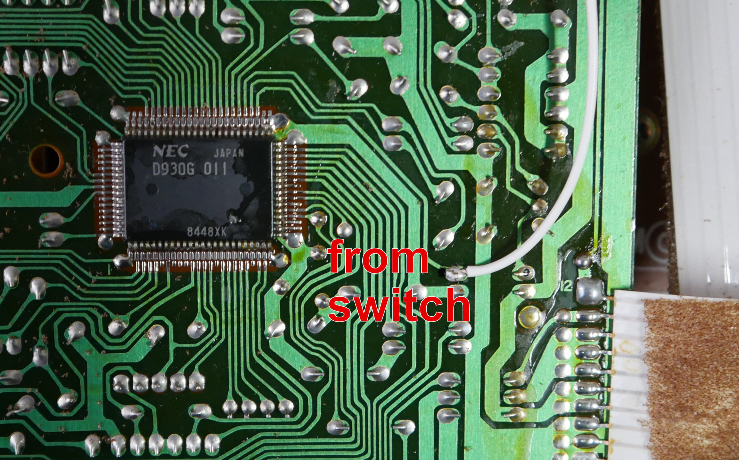
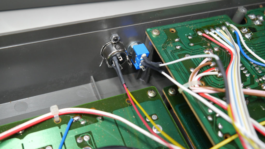
If you want to sync the CT-410V to MIDI clock, there is one additional signal: The clock signal is at IO21. This wire (yellow below) is soldered to a switch mounted in the back. With this switch, you can select between the MIDI clock and the original clock. From this switch, a wire is soldered to the clock injection point (see picture)

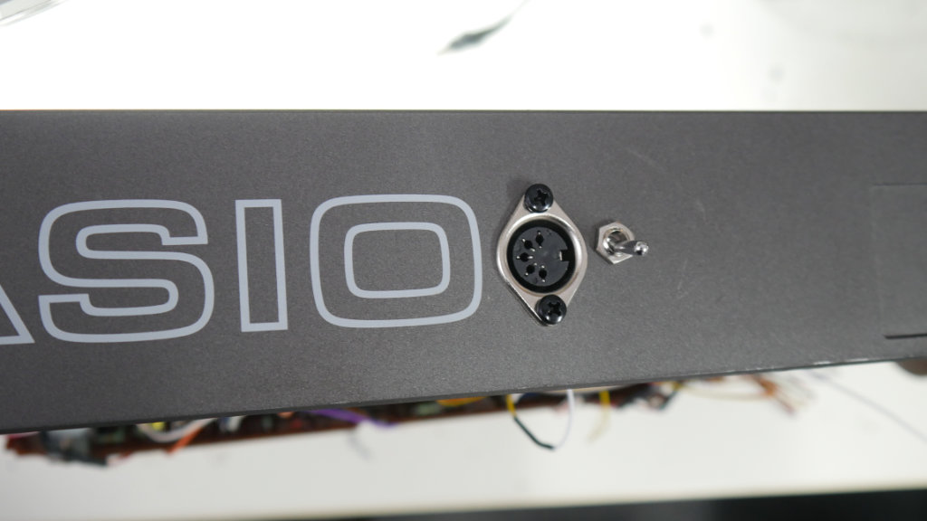
The MIDI connector is plugged into the MIDI-in connection of uniMatrix. We mounted both the MIDI socket and the switch on the back. The holes for the MIDI socket can be easily drilled using the provided drill-aid.

Using the uniMatrix configurator, load the configuration for CT-410V (right click, save-as) and send it to uniMatrix.

Congratulations, you can now play your CT-410V via MIDI !

MIDI for Casio MT-90 with uniMatrix

This guide explains how to install a MIDI input in a Casio MT-90 keyboard. We use uniMatrix to interface the keyboard matrix and simulate key presses.

uniMatrix can also sync the internal rhythms to MIDI clock. Start/stop is provided via MIDI CC 68, but this can be changed using the configurator.

It is also possible to change instruments via MIDI program change messages and to select rhythms via MIDI CC.

ProgCh 0: Piano
ProgCh 1: Elec Piano
ProgCh 2: Organ
ProgCh 3: Oboe
ProgCh 4: Clarinet
ProgCh 5: Vibraphone
ProgCh 6: String
ProgCh 7: Elec Organ

CC 7: Rock
CC 8: Swing
CC 9: Walz
CC 10: Bossa Nova
CC 11: Slow Rock
CC 66: Sustain
CC 67: Casio Chord
CC 68: Start
CC 69: Stop

Installing uniMatrix

Use double sided tape to mount the uniMatrix board to the big IC on the MT-90 board. Then, solder the wires to the points shown in the picture below. The numbers are the uniMatrix I/O numbers. Do not rely on the wire colors in the picture, these might be different in your version of uniMatrix.
Solder the two power wires Vin and GND to the points shown.

Finally, drill a hole in the side using the drilling stencil provided in the kit, mount the MIDI socket using the two M3 bolts and plug it into the MIDI in connector of uniMatrix.

Using the uniMatrix configurator, load the configuration for MT-90 (right click, save-as) and send it to uniMatrix.

Congratulations, you can now play your MT-90 via MIDI !