How to install MIDI jacks the proper way

Introduction

When retrofitting midi to old gear using our kits, often holes for the midi sockets need to be drilled. This guide is how we do it and shows a clean, easy way using a hole punch.

Stuff you need:

  • Drill Aid
  • Center Punch
  • 2mm drill
  • 3.2mm drill
  • 4mm drill
  • 6mm drill
  • 8mm drill
  • Screw hole-punch 15.2mm
  • Box wrench 13mm
  • Electric drill


  1. Attach drill aid
  2. Punch the center holes

3. Remove drill aid

4. Drill 2mm pilot holes

5. Use 3.2mm drill

6. Use 4mm drill

7. Use 6mm drill

8. Use 8mm drill

9. Insert screw and skirt of the screw hole-punch

10.Attach the cutting part of the screw hole-punch

11.Use the box wrench, clockwise

12. Result

13. Install MIDI jack

That’s all. Have fun.


Unison mode for Korg Poly-61

p61uni1

While the older brother of the Korg Poly-61, the Polysix, features a monophonic ‘Unison’ mode, the Poly-61 does not. The reason is most likely the fact, that the Poly-61 is DCO based, making the voice spread technology used in the Polysix Unison mode not possible.

It is however nevertheless desirable to add a monophonic mode to the Poly-61. Playing a monophonic synth is quite a different experience compared to a polyphonic one and if you have extended features such as not retriggering the envelope when playing legato, a whole new world of sound opens up.

If you install the Modysix mod you will have this feature build in, the only problem is: There is no ‘Unison’ button. You can select the unison mode using Midi, but it is actually quite simple to install an extra button and led.

p61unischem

You only need four parts and a little bit of wire: A push button, an led, a diode and a resistor. The push button can be any kind of button, the one I chose is what I had lying around, but you can probably find one that looks more like the original buttons.  The diode is a general purpose one, such as 1N4148. For the resistor choose a value of your liking. I found that the value of 470 Ohms used for the other leds in the Poly-61 gives too much brightness with modern leds (led technology has vastly improved in the last 30 years), so you might use a larger value such as 1k Ohms.

p61uni2

After installing the switch and led in the front panel, you can connect them to the panel board labelled KLM-482 – it is the one the ‘poly’,’chord’,.. buttons are mounted on. Pin3 and Pin9 in the schematic above refers to the pins on the connector on that panel. You can find +5V where I connected the resistor in the picture above. As you can see, I soldered the diode and resistor directly on the back of the PCB.

p61uni3

The last connection goes from the LED to Pin6 of IC3. It can be found on the processor board (the one with the battery).

When finished you can now use the unison mode on your Poly-61. Have fun!

Polysix Mod PCB coming soon

I am currently working on a PCB / kit for my Korg  Polysix mod. It will be available soon and feature both mods: portamento and spread detune.

This is a design for a front panel – Polysix style:

p6moddesign

It could look like this:

p6moddesign2

And here is a rendering of the PCB:

p6 spread detune pcb

Currently a prototype board is being produced, for some last checks before a larger order of boards.

If you are interested, have any suggestions or questions, let me know in the comments 🙂

Adding output capability to a 10€ logic analyser

What is this?

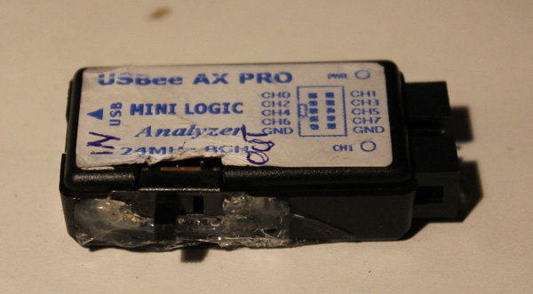
I got myself one of these cheap USB logic analyses for about 10€. You can order these directly from china, free shipping, for example at dealextreme or aliexpress.

Unfortunately the hardware only supports digital input but not digital output even though the software does. But as it turns out you can add output capability with a nice small hack. This way you get a logic analyzer, a frequency generator, frequency counter, PWM generator, arbitrary digital signal generator,….! All in one.

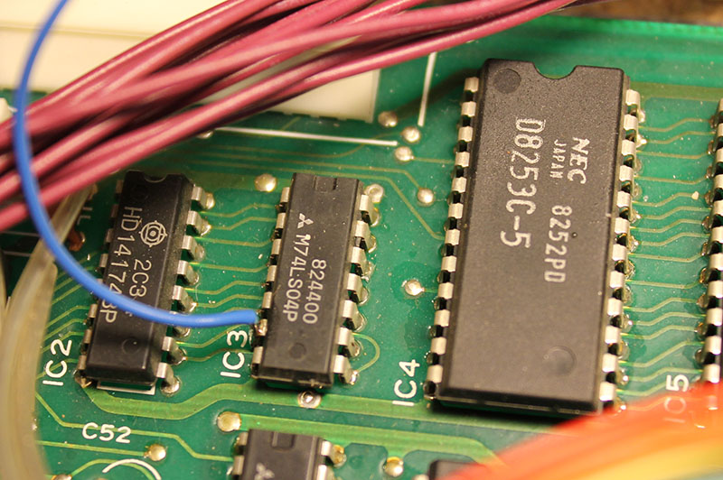
The hardware of the LA basically consists of a CY7C6813A which handles the USB communication and a HC245 bidirectional bus driver. Yes bidirectional! A little debugging showed that the CY7C6813A as a matter of fact does output digital signals, when requested by software.

The only problem is, that the direction pin of the HC245 is hardwired to input mode.

Howto

You need:

  • A soldering iron with a small tip
  • A 10k resistor (or any other value between, let’s say 10k and 100k)
  • Some enamelled copper wire
  • A little switch
  • maybe some super glue

lamodboard

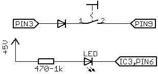
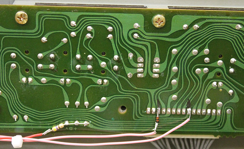
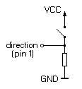
Take a knife or a scalpel and cut the trace marked in red. Solder the resistor to the contact marked as GND and use the enamelled copper wire to connect it to the pin which was connected to the trace you cut.

Take a small switch – I just took what I had lying around – and connect it to VCC and to the direction pin.

lamod

IMG_3429

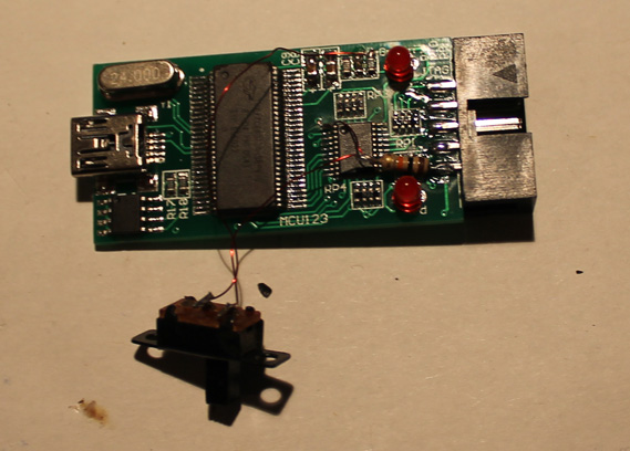
You can use the knive to cut an opening for the switch into the case and then use the super glue to glue it in. Done…

So now you can switch between input and output mode. Just be careful not to leave any outputs connected to the device when putting it into output mode.

lacase

(I used hot glue instead of super glue so it looks kind of ugly, but I don’t care 😉

This is a 1Mhz signal at the output:
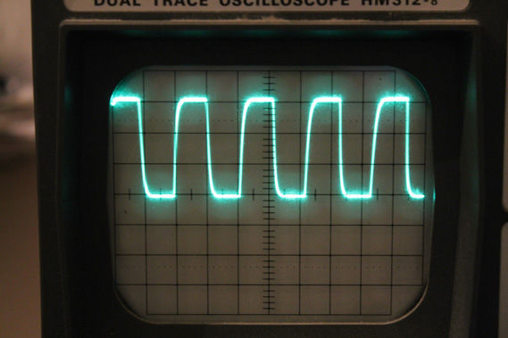
IMG_3431

Have fun!!

There is a nice writeup about which software you can use on the ePanorama Blog

update: A lot of people (including myself) had problems with the USB cable that came with the LA. I couldn’t even charge my phone properly with it. So if you ever experience problems with high sample rates, glitches, etc, replace it.
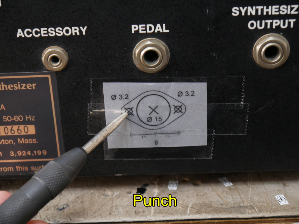
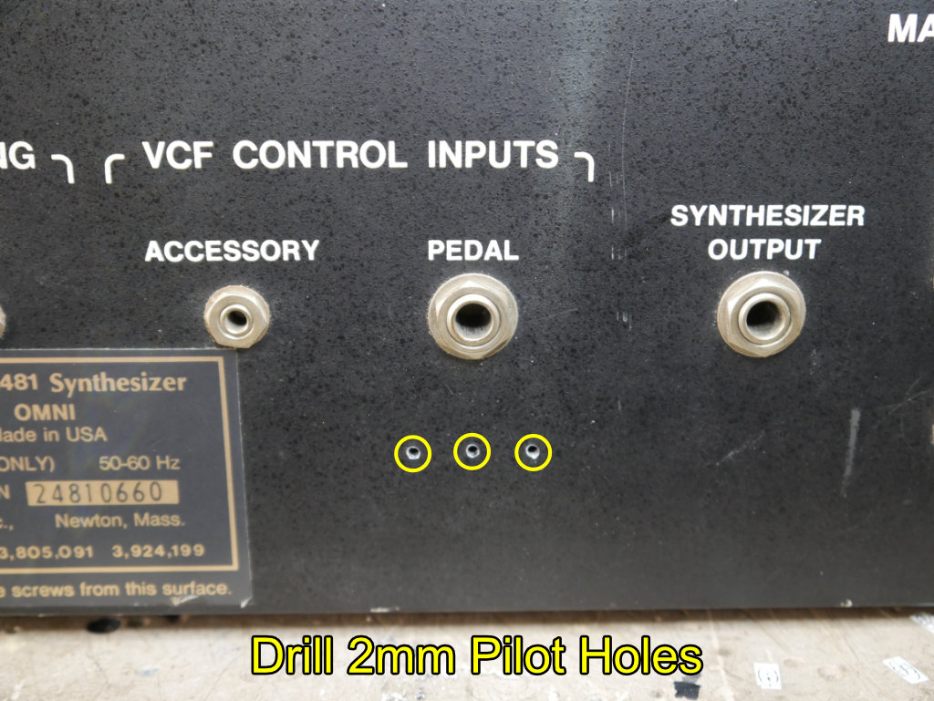