Repairing a Novation Supernova with an overvoltage damage

This Novation Supernova just came in.

probably due to overvoltage on one of the outputs two of the outputs failed.

Which is actually really lucky, take a look at the damage!

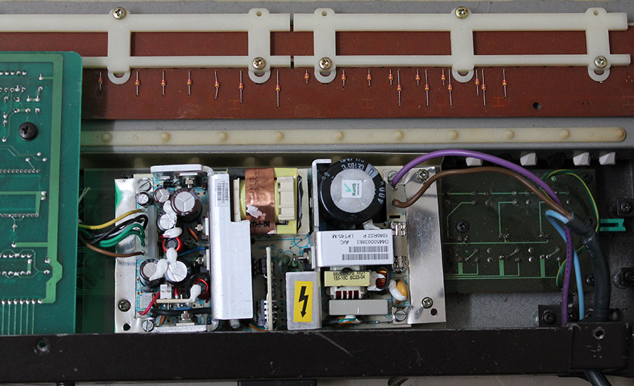
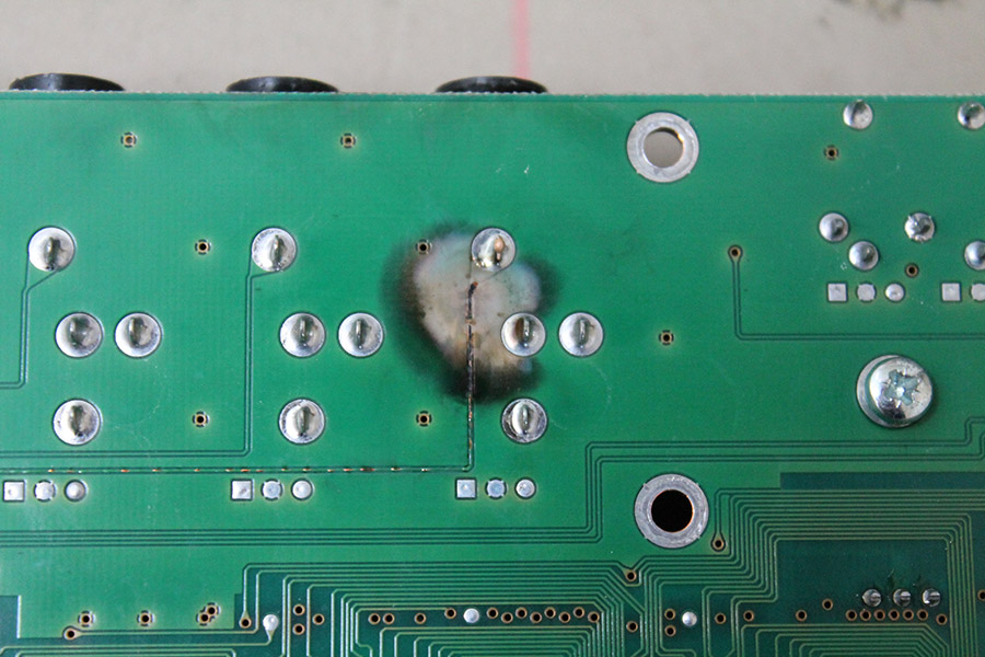
This is the bottom side of the PCB, the trace coming from the connector vaporized and you can see how much heat must have been there: A large area of the solder resist is gone too. If you look closely you can see, that the trace actually fused with the surrounding ground plane. I believe this is what saved the Supernova, because it protected the rest of the circuitry from the high voltage.

Novation Supernova (2)

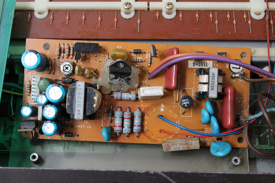
This is the other side. I already desoldered the connectors. As you can see there was a lot of heat here, too, the trace acted like a fuse and melted and the 47Ohms resistor exploded. Wow!

Novation Supernova (1)

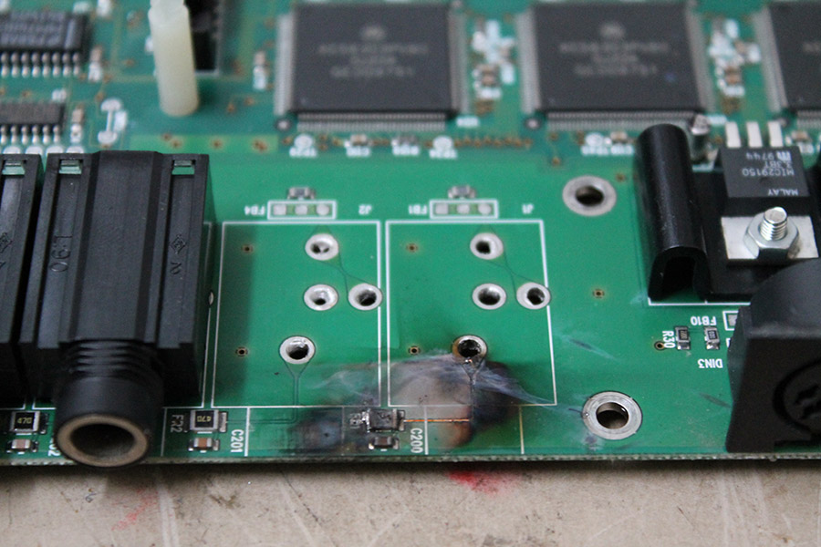
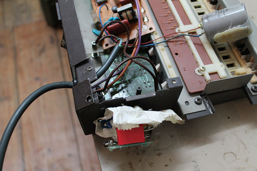
These are scorch marks on the metal enclosure which was about 1cm away from the PCB.

Novation Supernova (3)

Apart from that only some more resistors and an op-amp failed. Amazing when you consider what must have happened here!

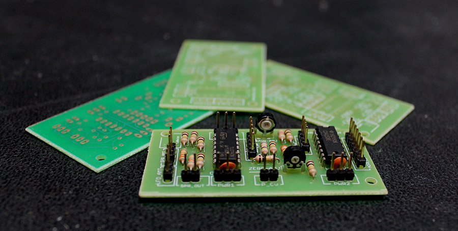
I replaced the broken SMD components, redid the broken traces and the two outputs are working again 🙂

Novation Supernova (8)

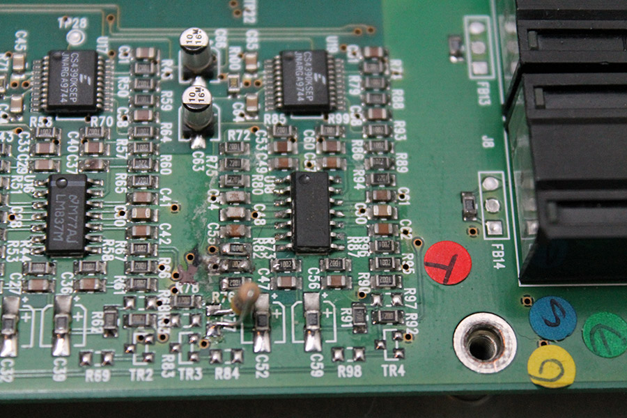
In the picture above you can see the replaced opamp and some replaced resistors. Unfortunately I didn’t notice a broken 740 ohms resistor before I ordered the parts. I used wired one instead, doesn’t look as nice, but works as well.


A new power supply for a Yamaha DX21

Look at this horrible “repair” job someone did to the power supply of this Yamaha DX21 (which broke again of course)

The main electrolytic capacitor has been replaced with just some other one, definitely not a low-ESR type, connected with quite long and thin leads and then glued into place somewhere in the case. The switching transistor is glued into place too and the traces leading to it are almost, but just not quite broken.Yamaha DX21 (3)

An additional power LED had been added, but instead of connecting it to the 5V rail, it is connected directly to 230V via an capacitive “led power supply”.

Yamaha DX21 (2)

Last but not least there is some strange sticky stuff all over the place, might be electrolyte from the capacitor, or some kind of glue that was used for something. It is hard to tell, it is an awful mess in there. Yamaha DX21 (1)

In cases like this instead of trying to fix the existing power supply it is better and cheaper to replace it with a new one.

Yamaha DX21 (4)


Sequential Tom power supply

This Sequential Tom needed a new power supply. It states to need 15V AC, but after a little bit of reverse engineering it turned out to actually need 2×7.5V AC. It is quite unlikely to find a wall adapter with 2×7.5V AC, so I had to build an own power supply. It is just a (fused) transformer in a case, and a plug attached to a cable that fits into the back of the Tom. Done 🙂

sequential tom (2)

4x Midi CV Interface rev.2

While waiting for my Polysix mod PCB, I am working on rev. 2 of my midi to cv interface. Rev 1 was working well, but I realized I wanted some more features.

midi2cv4

The new one will have:

  • 4 x CV out, 12 bit precision each
  • 4x Gate
  • Glide / portamento control for CV outs
  • For each CV you can switch glide mode between (on/auto/off)
  • For CV 3/4 you can choose individually whether they output midi notes or midi velocity from CV 1/2
  • Each CV can be controlled by midi notes and midi controller
  • FM in
  • Midi learn
  • Leds for gate and CV out
  • Doesn’t use smd parts an can be built by everyone

This basically enables you to have 4x polyphony with a modular synthesizer !…..and much more 🙂


Polysix Mod PCB coming soon

I am currently working on a PCB / kit for my Korg  Polysix mod. It will be available soon and feature both mods: portamento and spread detune.

This is a design for a front panel – Polysix style:

p6moddesign

It could look like this:

p6moddesign2

And here is a rendering of the PCB:

p6 spread detune pcb

Currently a prototype board is being produced, for some last checks before a larger order of boards.

If you are interested, have any suggestions or questions, let me know in the comments 🙂

Adding output capability to a 10€ logic analyser

What is this?

I got myself one of these cheap USB logic analyses for about 10€. You can order these directly from china, free shipping, for example at dealextreme or aliexpress.

Unfortunately the hardware only supports digital input but not digital output even though the software does. But as it turns out you can add output capability with a nice small hack. This way you get a logic analyzer, a frequency generator, frequency counter, PWM generator, arbitrary digital signal generator,….! All in one.

The hardware of the LA basically consists of a CY7C6813A which handles the USB communication and a HC245 bidirectional bus driver. Yes bidirectional! A little debugging showed that the CY7C6813A as a matter of fact does output digital signals, when requested by software.

The only problem is, that the direction pin of the HC245 is hardwired to input mode.

Howto

You need:

  • A soldering iron with a small tip
  • A 10k resistor (or any other value between, let’s say 10k and 100k)
  • Some enamelled copper wire
  • A little switch
  • maybe some super glue

lamodboard

Take a knife or a scalpel and cut the trace marked in red. Solder the resistor to the contact marked as GND and use the enamelled copper wire to connect it to the pin which was connected to the trace you cut.

Take a small switch – I just took what I had lying around – and connect it to VCC and to the direction pin.

lamod

IMG_3429

You can use the knive to cut an opening for the switch into the case and then use the super glue to glue it in. Done…

So now you can switch between input and output mode. Just be careful not to leave any outputs connected to the device when putting it into output mode.

lacase

(I used hot glue instead of super glue so it looks kind of ugly, but I don’t care 😉

This is a 1Mhz signal at the output:IMG_3431

Have fun!!

There is a nice writeup about which software you can use on the ePanorama Blog

update: A lot of people (including myself) had problems with the USB cable that came with the LA. I couldn’t even charge my phone properly with it. So if you ever experience problems with high sample rates, glitches, etc, replace it.


Repairing Yamaha DX100 keyboard

Yamaha DX100 (7)

So the story goes like this:

The previous owner in a desperate attempt to fix a partially broken keyboard managed to scrape of all the conductive material from the rubber strip.

Usually when I fix rubber pad based keyboards like this, it is usually enough to put some graphite spray on a Q-Tip and gently apply some of it to the pad. In this case none of the keys where working and even though the usual approach brought back some keys, it didn’t work very well. So I decided for a full renewal:

Yamaha DX100 (2) Yamaha DX100 (3)

Cover all parts of the rubber contacts that shouldn’t be conductive…Yamaha DX100 (4)

…use some nice graphite spray….Yamaha DX100 (5)

…woooo….Yamaha DX100 (6)

…and put it back in.

The Yamaha DX100 works again like a charm 🙂