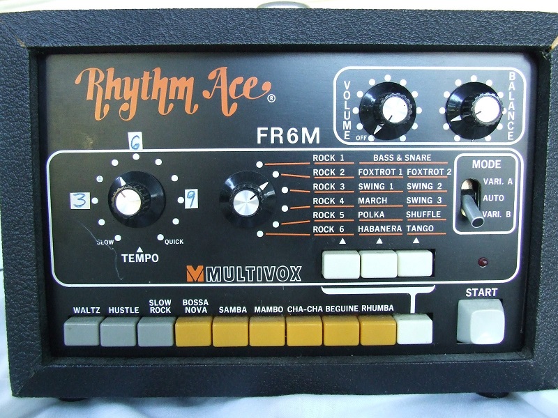
This manual shows how to install uniPulse in a Korg MiniPops 3 (aka Univox SR-55 and Aria Diamond) and trigger all 9 instruments via midi.
The installation is fairly simple and only requires soldering a few wires and parts into place, as well as drilling a hole for the midi socket.
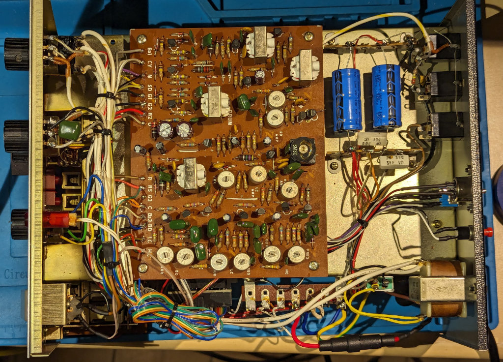
Trigger connections
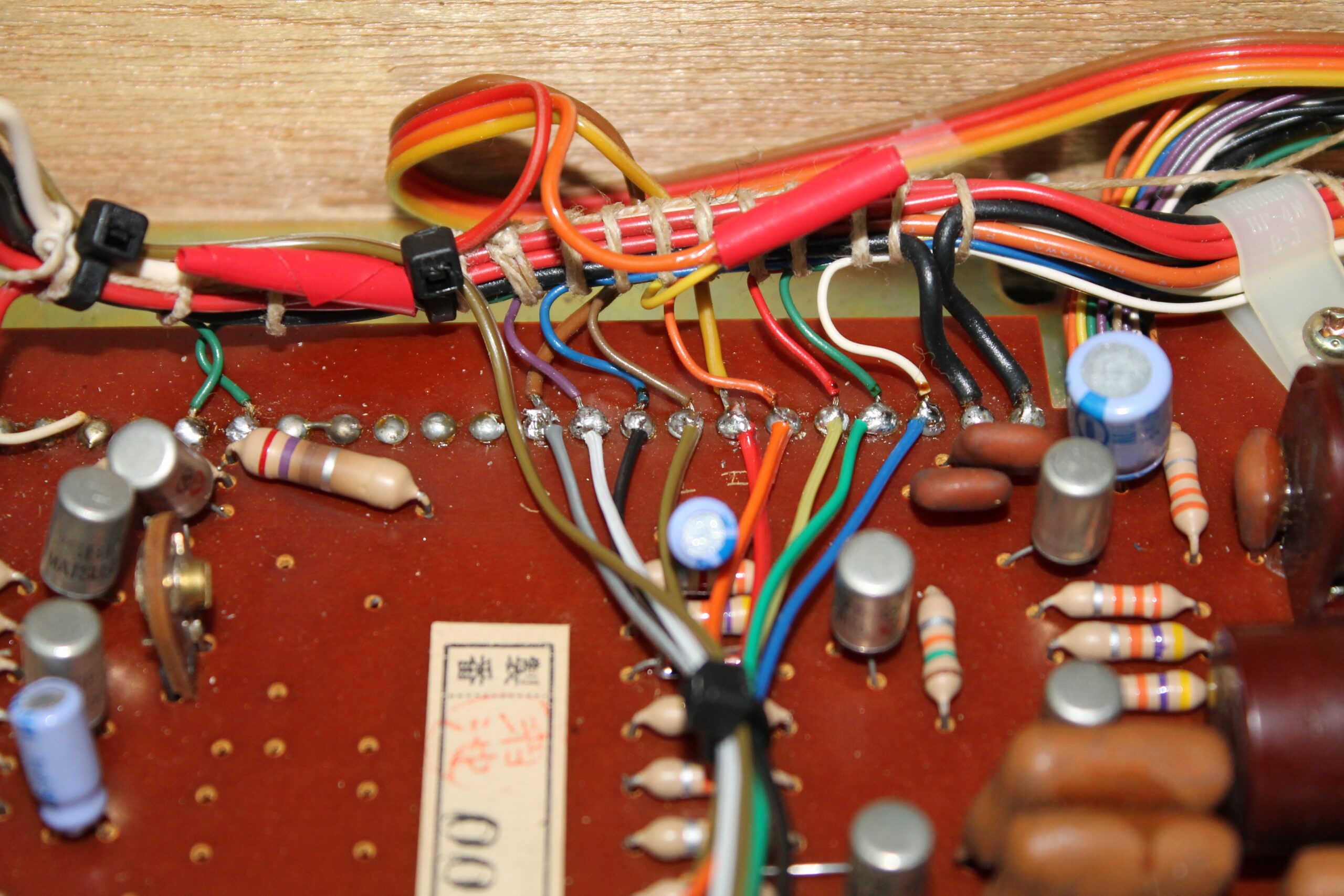
Here we see the 9 trigger points for the various instruments. These are trigger outputs P1-P9 from uniPulse directly soldered to the trigger points.
uniPulse power supply
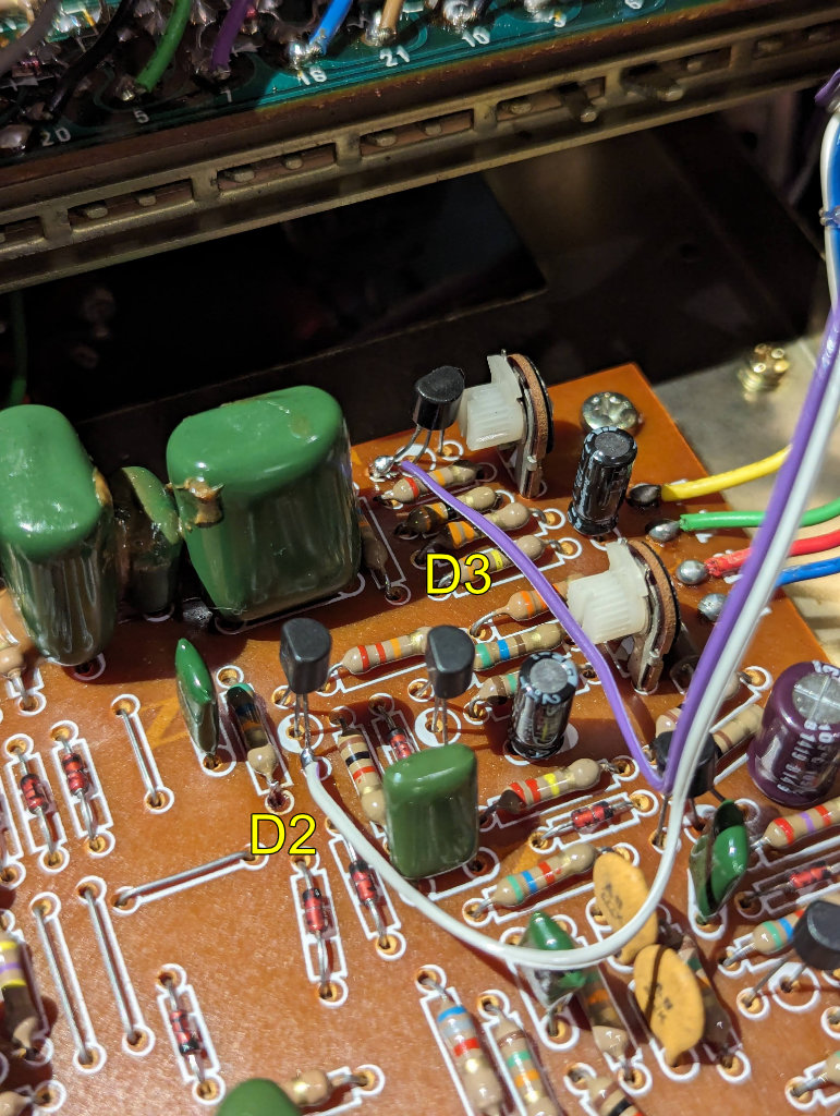
In order to power the uniPulse you need to add a few parts, but it is rather simple. The following image shows how we added an additional diode resistor and capacitor in order to get a positive supply voltage for uniPulse. These parts are included in the kit on request. This is a 100uF capacitor, a 1N4148 diode and a 2k resistor. The resistor avoids high voltage spikes, its value is not critical. A 2.2k resistor can also be used.
As you can see the capacitor is connected to the black GND connection with its negative pin, the diode feeds a positive voltage to its positive pin. The resistor is soldered across the capacitor. The brown +V wire from uniPulse is connected to the positive side of the capacitor.

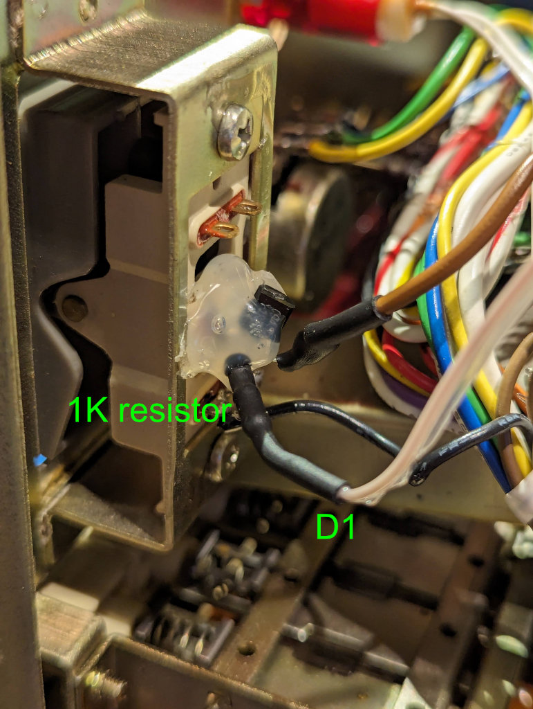
Ground connection (red GND wire from uniPulse) can be connected at the point seen below.
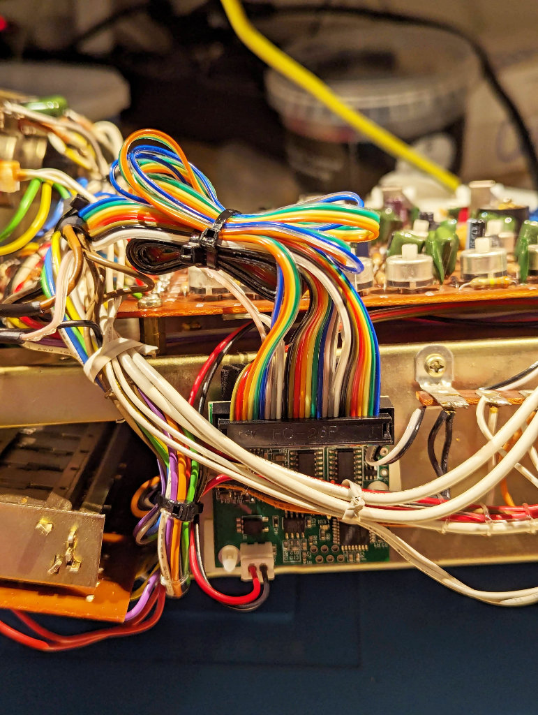
 Installing the midi socket
Installing the midi socket is simple. A drill guide is included in the kit. Any location is fine, we chose to install the socket in the cable compartment of the machine. The white marking on the midi connector points inwards on the uniPulse board.
Config file upload
After installing uniPulse, turn on the machine and make sure the LED on the uniPulse is turned on. This means it has power and is running.
Connect midi and use the config tool to upload the following configuration.
Config file (right click, save as)
have fun!