ELKA Drummer One uniPulse installation

This manual shows how to install uniPulse in the ELKA Drummer One and thus allows to trigger voices via midi and to sync the Drummer One to midi Clock.

Thank you very much to Thomas Kayser of SynthMedic for figuring this out and providing pictures.

After installation use the Config Tool to upload the Config file for ELKA Drummer One (right click, save as).

Connecting trigger points

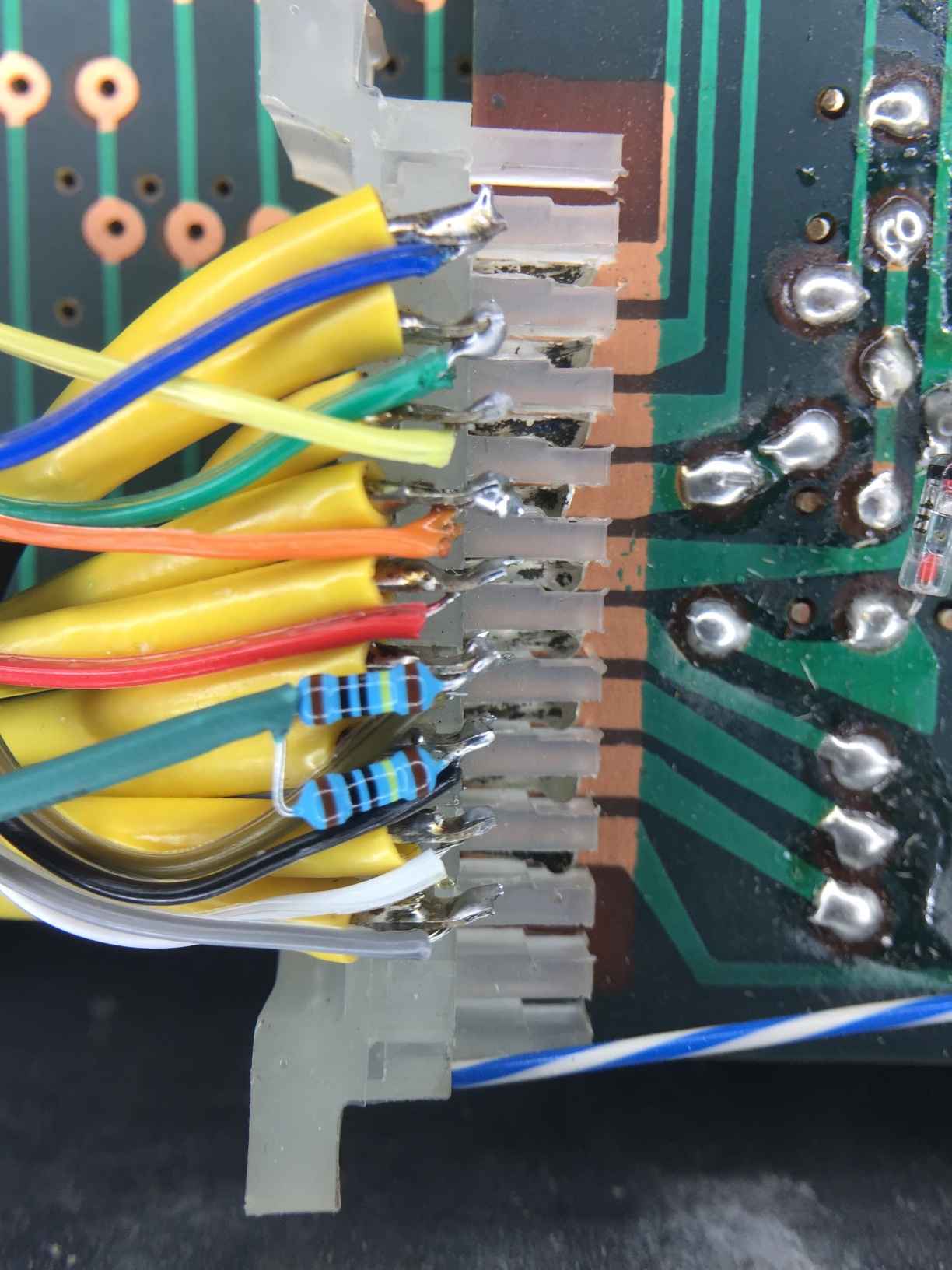
Below you can see the installed uniPulse. Trigger points are on the right the picture below shows the trigger points in a bit more detail. Two of the triggers needed additional 1Meg resistors to ground which can also be seen in the picture. UniPulse channels 1-9 are used.

Midi Clock Sync

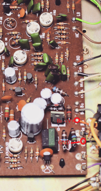
If you like, you can also sync the Drummer One to midi clock. This requires a bit of additional circuitry. A two-pole switch is used to switch between internal and midi clock. This switch is provided with the uniPulse kit since uniPulse MK2. You will also need two general purpose NPN Transistors and 2x10k and 2×2.7k resistors. The circuit can be seen below. Its purpose is to level shift the clock and gate voltages.

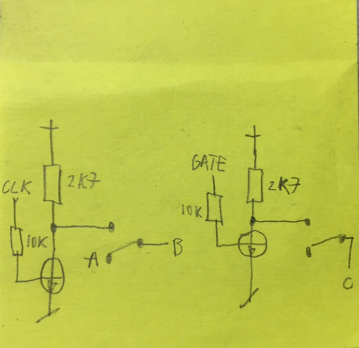
The GATE signal is connected to uniPulse pin D1, the CLOCK signal to uniPulse pin D2.
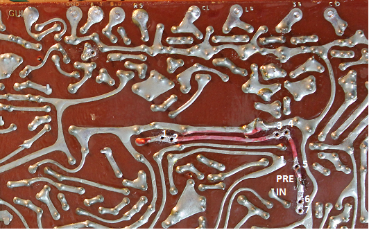
The picture below shows the location of the C point and the circuit on a prefboard. To access points A and B, one leg of a capacitor needs to be desoldered. This is also shown in the picture below and in more detail in the next picture.

Installing the uniPulse board

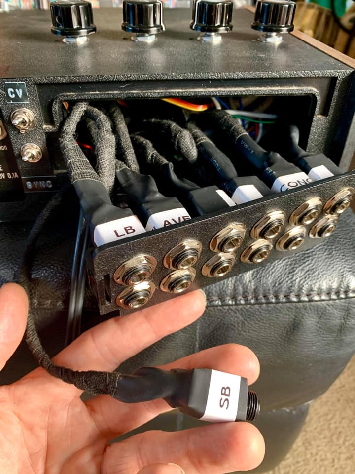
You can mount the uniPulse board in the case using distancers as shown here:

The Drummer One needs to be in start mode with all Rhythms deselected in order to be synced to midi.

Roland TR-66 unipulse Installation

A customer sent us the uniPulse trigger points for the Roland TR-66. Thank you very much! Installing is very simple, just connect the unipulse to the trigger points as shown and upload the config file via the tool.

As you can see there are 9 instruments you can trigger:

BD = Bassdrum
SD = Snare Drum
HH = Hihat
CY = Cymbal
HC = High Conga
LB = Low Bongo
HB = High Bongo
C = Conga
RS = Rim Shot / Cow Bell

Just connect uniPulse outputs P1 .. P9 to these points, configure these outputs using the configurator as ’15V, negative, Open Rect’ and you are good to go.

When the bossanova rhythm is selected, you will hear the Rim Shot. If no rhythm is selected, the cowbell will sound.

uniPulse needs some Power and you can get it by connecting uniPulse GND to G1 or G2, and connect uniPulse V+ to B0 of the voice board as shown in the next picture.

Have fun!

uniPulse MK2 is here

uniPulse has been updated to a new improved MK2 version, while the price stays the same.

These are the improvements:

  • Larger output voltage range: +-15V
  • Wider supply voltage range: runs from 7V-25V, generates +-15V supply voltages internally
  • 3 additional digital outputs
  • Improved input and output protection
  • Fully compatible with uniPulse MK1
  • Comes with an external midi socket with wire and connector
  • Now also included in the kit:
    • A two-pole throw switch often needed to switch between internal and midi clock
    • A panel mount learn button which can optionally be installed

µTune: Recalibrate CV-input

Early models of µTune were unfortunately shipped with a badly calibrated CV-Input.
This only concerns you if you have one of the early models with HW version 16 or 17. And only if you have firmware version 1.00 installed.
If you have Hardware version 18 or higher or firmware 1.01 or higher, you can stop reading now.

Continue reading

Boss DR110 uniPulse install

This manual describes how to install uniPulse in a Boss DR-110. If gives you velocity sensitive trigger of the instruments, accent trigger and midi clock sync.

There are two additional sounds that can be triggered via midi: Part of the clap (electric snare) and part of the cymbal.

For the DR-110 you need to get the custom DR-110 uniPulse version.

Installing the kit does not require to cut any traces and is generally a simple soldering job. You do however need to drill a hole for the MIDI socket. We use a 3.5mm jack socket and include an adapter. If you require, you can also install a DIN-socket, but it only barely fits. You also need to install 2 additional switches: One switch to select the clock source (MIDI or internal). The other to switch the bassdrum trigger from MIDI to internal.

MIDI is received on channel 10 with the following notes:

Note

Name

35

Bass Drum

38

Snare

39

Clap

40

Electric Snare (extra sound)

42

Closed Hihat

46

Open Hihat

49

Cymbal

51

Extra Cymbal

33

Accent on/off

Installation manual as PDF

Individual Outputs for Korg Mini Pops 7

After installing the UniPulse in your Korg Mini Pops 7 you can also add individual outputs for each instrument.

Picture by Telharmoneum, Install by Simon Ayton

Fifteen different outputs are available, but of course you can only install some of them – for example 12 like in the picture above.


PRE IN Bus

Many of the instruments are connected to the “PRE IN Bus” which is marked red in the schematic. To gain access to each instrument connected to the “PRE IN Bus”, you have to desolder one pin of each resistor connected to it. Leave the other resistor pins connected.
It is not too easy to find the resistors on the board itself so numbered the spots where you have to desolder the pins.

schematic-instruments_bus

schematic-board_prein

Pre-in connections – overview

Pre-in connections 1 – 7

Pre-in connections 8 and 9

1 – 47k (Rim Shot)
2 – 33k (Claves)
3 – 82k (LB)
4 – 330k (SB)
5 – 100k (Conga)
6 – 82k (CB)
7 – 68k (CB)
8 – 680k (SD1)
9 – 470k (SD2)

Now solder the jack’s signal pins to the resistor pins.We used switched jacks. This way the instruments will be connected internally when nothing is plugged in.
jack_configuration

Note that the 68k and the 82k of the cowbell have to be soldered together, unless you want to have both parts of the CB sound available independently.
cowbell_resistors

Percussion

However not all instruments are connected to PRE IN.
The following instruments just need a direct connection from the board to the sockets: TAM, GUI and QUI. The solder points are marked below.
schematic-instruments_percussionboard_rueckseite_percussionBase Drum, High Hat, Cymbals

Originally the base drum, high hat, cymball and the percussion instruments are mixed together. To separate the instruments you again have to desolder several resistor pins as marked in the following pictures. The spots where the cuircuit is opened are marked by two black lines. Once again you have to use switched jacks to close the circuit as long as no male jacks are inserted.
schematic-instruments_base_hiha_cym

1 – 47k (BD)
2 – 330k (HH)
3 – 47k (CY)

Solder wires from the desoldered resistor pins to the socket’s tips and from the socket’s switch contact back to where the resistors were connected originally (marked in the picture above).

Ground

All output sockets need a ground connection. Any point labelled GND on the board will do.

The final result could look like this (image by Telharmoneum, thank you very much!)

ModyPoly for Poly-61M

This is a quick manual how to install the ModyPoly in an Korg Poly-61M. The existing midi sockets are used, so no new holes have to be drilled. Incomming midi messages are passed to both the original midi implementation and the ModyPoly. Outgoing midi messages will be from ModyPoly only.

Continue reading