
This manual explains how to install the Tubbutec UniPulse in a Rhythm Ace FR3. After the installation you can trigger the individual instruments via midi and optionally also sync the machine to the midi clock. Apart from this manual we recommend reading the general uniPulse manual.
IMPORTANT:
The FR-3 is (so far) the only drum machine for which uniPulse needs a separate power supply. This can be an additional 12V wall adapter for example, or a small switch mode supply or transformer built into the FR-3.
The UniPulse config file for the FR3 can be found here.
The video below shows a little demo of an installed kit.
Installing the PSU
The FR-3 uses a full-wave rectified supply voltage of -15V. In this case we need to install an additional power supply, as explained in the UniPulse user manual. We used a small switched mode supply, but a small transformer is equally adequate. In both cases the UniPulse GND must be connected to the FR3 GND.
Here you can see the placement of the power supply. As there is not much space anywhere else in the FR3 we chose to install the PSU in the cable department

PSU placement
Power supply wiring: we chose to desolder the 2 wires from the power switch to the transformer and use Wago terminals to distribute power to the internal transformer and the Unipulse power supply.

Wiring for the Unipulse PSU
Installing the UniPulse
On the back of the FR3 is a compartment for storing the power chord. We decided to install the midi socket here. This way it is out of sight if not used. Of course it is possible to install the socket anywhere on the machine.
Place the stencil provided with the UniPulse and mark the location of the holes with a center punch. Drill the holes and use a deburrer to remove any excess metal.
Use the two screws provided to fasten the UniPulse behind the panel. Make sure that the learn button can still be pressed, if necessary make the hole for the button a bit larger.

MIDI jack location in the cable department
Drum trigger points
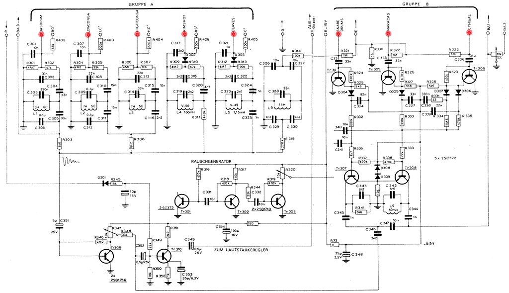
The next step is to connect the ribbon cable to suitable trigger points. Often the trigger points are easily identifiable. This is also the case here. The image below shows the trigger points for the eighth instruments of the FR3 and how to connect them to pulse outputs P1 – P8.

Trigger points and Gnd connection (connect the orange Gnd wire from Unipulse here)
You can also see the trigger points in the schematic below. This schematic was taken from a 1970 issue of electronics magazine Elektor and might contain errors.
After loading the config file for the FR3 using the uniPulse config tool, you can already trigger it via midi. All instruments are fully velocity sensitive. In our configuration the length of the pulses is linked to a midi controller, which can be used to alter the sound of the drums. You can edit the config, try different pulse shapes, link the length to other sources or change the midi mapping.
In order to get the FR-3 to sound properly, the start switch needs to be set to on. This will of course also start the machine, but you can deselect all rhythms using the rhythm select buttons.
Rhythm Ace FR3 configuration in the UniPulse configurator
Clock and start/stop
The next steps are completely optional and allow you to sync the FR-3 to a midi clock, including start and stop.
The picture below shows the clock part of the FR-3 schematic. Again this was taken from Elektor 19700 and might contain errors..
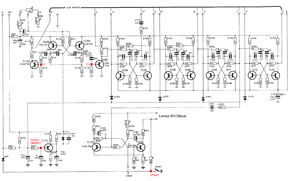
Clock of Rhythm Ace FR-3 with sync injection points
The clock circuit of the FR-3 consists of a master clock (with adjustable speed via a potentiometer) and four flip flops to divide the clock – a binary counter. Here, apart from the positive clock output of the master clock (C+), which is passed to the first counter stage, an inverted output of the clock is also extracted. This is used to create the ‘swing’ rhythms of the FR-3, and we need to take this into account when feeding a clock to it. Without this inverted clock, parts of the swing rhythms are simply missing.
Luckily the UniPulse can create multiple simultaneous clocks with adjustable phase, so we don’t have to build an additional inverter. More about this later.
We also want to be able to start and stop the clock synced to the midi clock. In the Fr-3 the Start switch has multiple functions: If it is switched on, the flip flops are put into a reset state which stops the clock. Additionally the volume of the output amplifier is lowered (via the R line) and the indicator lamp is switched off.
When we sync the machine remotely, we want to use our own clock and start/stop signal. One way to do this is illustrated in the schematic below:
A switch is used to toggle between the internal clock and the external midi clock.
If the switch is in its normal position, the internal clock works as normal.
Setting the switch to ‘external’ will pull CLOCK INHIBIT to ground, which stops the internal clock. Additionally the external start/stop signal is routed to the start stop switch.
The way this is done is a wired-OR with the original switch, which means it has to be set to ‘start’ in order to work. Alternatively the internal start switch could be disconnected from the circuit instead.
A level shifter (identical to the one presented in the UniPulse manual) is used to translate the 5V UniPulse gate to -25V. The clock signals are injected using a 10k resistor and 100nF capacitor in series.

Level shifting circuit
The next picture shows the installed parts.
![]()

Clock circuit
Here you can see the start wire coming from the switch soldered to the start line, -25V and Gnd connection to the switch. For the 5V, D4 and Clock Inhibit connections see the level shifting circuit diagram.

Switch