This is how to install the uniPulse in a CR-5000 or CR-8000.
Update: User ‘a.d.a.m.baby’ on MuffWiggler found some great additions to this manual.
Here are the schematics and pictures with trigger points. Points in blue must be triggered with a negative voltage, points in red with a positive one. You can connect the uniPulse trigger outputs directly to these points. Use the configuration program to program the behaviour and polarity of the trigger outputs. Trigger points can be found on the bottom of this post.
Here is the schematic with the trigger points.
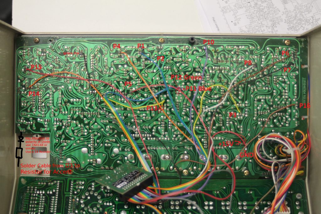
On the next picture you will see the whole CR-8000 voiceboard with the cables connected to each trigger point. Open the picture (download it) and zoom in to see where exactly the trigger points are.
If you want to trigger the Accent, solder the cable from D3 to a 1k Resistor and a Diode (1N4148 or similar; Polarity like shown in the picture) and the other end of the diode to the trigger point. In the config file provided accent is triggered via a midi note. If you prefer accent to be triggered if velocity is at 127, you can configure D3 as ‘Accent’ in the config tool.
UPDATE: We changed the location of the power connection for the UniPulse due to better performance!!! See the picture below. The brown Vin cable must be connected somewhere else!
They are labeled P1 to P16 corresponding to the uniPulse trigger outputs and colors.
Connect the brown Vin cable from UniPulse to the left leg of C22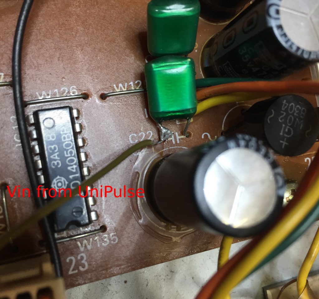
Midi sync CR-8000
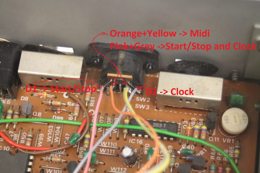
For the CR-8000 sync is very easy to install as it has a din-sync input. Just connect two digital outs of the uniPulse to the DIN-SYNC start and clock lines and configure the outputs with the configuration program.
You don’t even have to drill a hole for the midi socket – you can use the existing dinsync socket without losing its functionality because pins 4 and 5 are not used.
Midi sync CR-5000
In order to add midi sync to the 5000 you need to cut the two traces coming from IC15 as shown in the schematics below. You then add a two pole switch and connect it to two digital outs of the uniPulse. Configure the outputs as clock and start/stop. You can now use the switch to change between internal and midi clock.
MIDI and DIN Sync
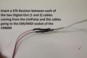
Solder a 47k Resistor between D1 and the cable running to the DIN-Connector, do the same for D2. (if you put the uniPulse to the same position we did, the cables from the uniPulse may not be long enough, thats why the cables have a different color on the DIN-socket) See attached pictures.
You need to cut the wires from the MIDI-connector provided with uniPulse. Solder the cables the same way they were to the DIN-Connector of the CR-8000. See again the picture above.
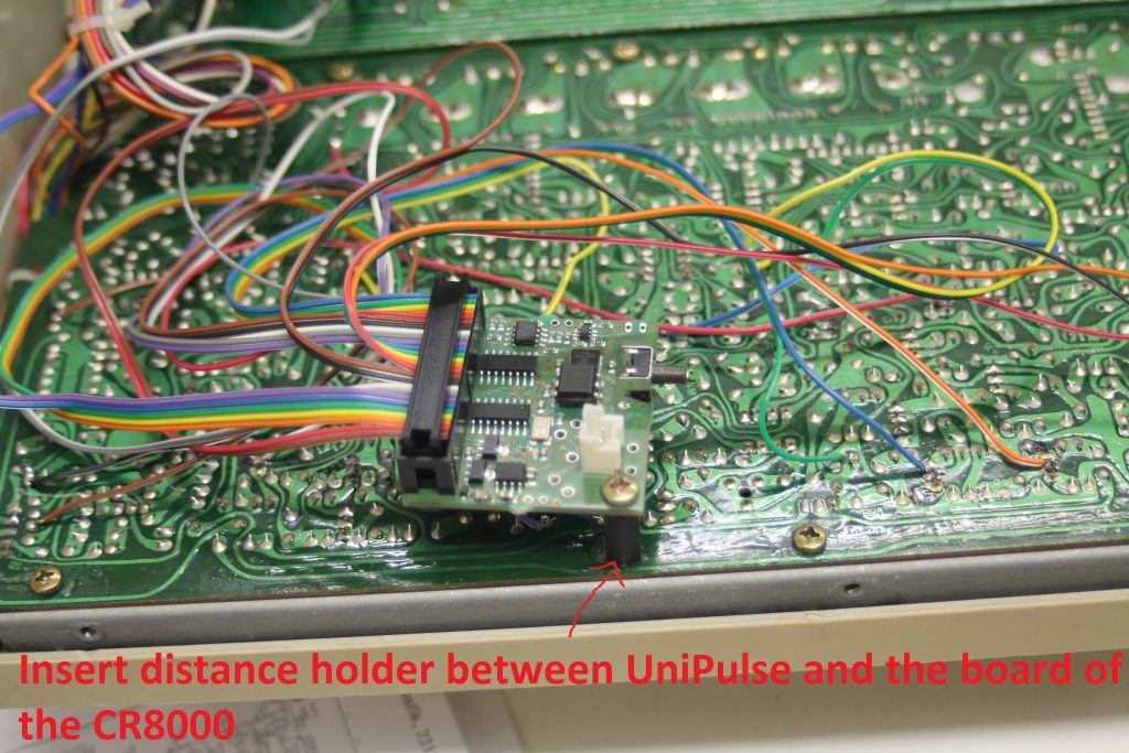
Now you can put the uniPulse in place. Use a distance holder screw. You can also find a different place to put the uniPulse if you like.
Finally you only need to upload the CR-8000 / CR-5000 config file to the uniPulse and you are ready to rock!


